

Converting a standard bike to an e-bike using a mid-drive motor is a rewarding project that can transform how your bike climbs, accelerates, and handles. This guide focuses on open mid-drive systems you buy and install yourself, not closed integrated systems from major OEMs.
⚠️ A Word Before You Start
This guide applies to open/DIY mid-drive kits — the kind you source and install yourself. It does not apply to closed mid-drive systems, such as those from major OEMs, which have their own proprietary installation processes. Beyond that, even within open kits, exact bolt sizes, torque specs, spacers, and menu layouts vary by brand, so always keep your specific kit’s manual open next to this guide.
00 Before You Begin: Tools And Key Concepts

Tools You Will Need
Before touching the bike, gather everything on this list. Reaching a critical step without the right tool is one of the most common reasons a mid-drive installation stalls halfway through.
Bicycle-Specific Tools:
- Crank puller: to safely remove the crank arms from the old bottom bracket spindle without damaging the threads.
- Bottom bracket removal tool: must match your specific BB(bottom bracket) type (cartridge, cup-and-cone, etc.); the wrong tool will slip and strip the BB.
- Pedal wrench: or a thin 15 mm spanner for removing the old pedals.
- The kit’s own spanner or multi-notch socket: most mid-drive kits include a special tool for tightening the motor’s main fixing nut; if yours does not, source the correct aftermarket tool before starting.
General Tools & Consumables:
- Metric Allen/hex key set (2–10 mm)
- Large adjustable wrench
- Torque wrench covering roughly 10–60 Nm — important for crank bolts and the motor fixing nut; guessing torque by feel on these fasteners is a common cause of long-term problems.
- Chain breaker tool or master link pliers
- Screwdrivers (flat and Phillips, for minor fittings)
- Side cutters or scissors for zip ties later
- Bicycle grease (for shell threads and contact faces)
- Clean rags and a small stiff brush (for cleaning the BB shell)
⚠️ Critical Warning
If you do not have the crank puller and the correct BB removal tool for your specific bike, stop and get them first. The bottom bracket removal is physically the hardest part of the process and cannot be done safely without the right tools.
Understanding Spacers Before You Start
This is the concept most guides mention briefly but never explain properly, and it causes real confusion during installation.
Most open mid-drive kits are designed around a standard BB shell width of 68 mm. However, many bike frames — particularly mountain bikes — use a 73 mm shell. When you install a motor designed for 68 mm into a 73 mm shell, there is a 5 mm difference that must be accounted for, otherwise the mounting plate cannot sit flush against the shell and the motor cannot clamp correctly.
This is why most kits ship with a small set of metal spacers — thin rings that slide onto the motor axle. Their purpose is to fill the gap between the motor’s mounting flange and the shell face so that when the main fixing nut is tightened, everything clamps evenly and the motor sits true.
How To Know If You Need Spacers And How Many:
- Measure your BB shell width before the motor goes in. If your shell is 68 mm and your kit is a 68 mm kit, you likely need no spacers or only minimal ones for fine adjustment.
- If your shell is 73 mm, you will typically need to add the 5 mm spacer(s) provided in the kit on the appropriate side of the axle.
- The clearest indicator during installation: after inserting the motor, if the mounting plate cannot sit fully flush against the BB shell with no visible gap, spacers are needed before tightening.
- Never tighten the main nut while a visible gap exists between the plate and the shell. Tightening over a gap does not close it; it simply bends or stresses the plate and gives you a false sense of security while the motor remains improperly clamped.
✅ Manufacturer Diagram
Always check your kit manual for its spacer diagram, as the exact placement — whether spacers go on the drive side, the non-drive side, or split between both — varies by kit design.
01 Phase 1 – Remove The Old Components
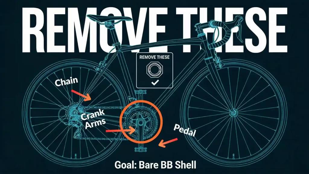
Before the motor can go in, you need to completely strip the existing drivetrain from the bottom bracket area. This means removing the chain, the pedals, the crank arms, and the bottom bracket itself. At the end of this phase, you should have a completely bare BB shell with nothing attached to it.
✅ Fast Track
If your bike is already stripped down to a bare BB shell, you can skip to Phase 2.
1.1 Remove The Chain
The chain must come off first because it runs through the crank area and cannot be left on while you remove the crank arms.
Create Slack
Shift the bike into the smallest gear at the front (smallest chainring) and the smallest sprocket at the rear. This gives the chain as much slack as possible.
Look For A Master Link
Look for a master link — a slightly different-looking link with a removable clip on the side. If your chain has one, use your fingers or master link pliers to squeeze the two sides of the link toward each other, then slide them apart to open. The chain will come apart at that point and can be lifted off.
If There Is No Master Link
If the chain is a standard continuous chain, use a chain breaker tool to push one of the link pins partially out until the chain separates. Do not push the pin all the way out; leave it slightly protruding so it can be reused if you plan to keep the chain.
Set the chain aside somewhere clean. You can reuse it if it is in good condition and long enough for the new setup, but many people fit a new chain during a conversion.
1.2 Remove The Pedals
This step trips up many beginners because of the threading. The left pedal is reverse-threaded. If you try to unscrew both pedals the same way, you will tighten one of them further into the crank.
- Right (drive side) pedal: standard thread — loosen by turning the axle counter-clockwise (the normal “lefty-loosey” direction).
- Left pedal: reverse thread — loosen by turning the axle clockwise.
Use a pedal wrench or a 15 mm spanner on the flat section of the pedal axle where it meets the crank arm. Pedals are often very tight, so use a long-handled wrench for leverage rather than forcing a short one. Set both pedals aside. You will reinstall them onto the new crank arms later.
1.3 Remove The Crank Arms
The crank arms are the two lever arms the pedals attach to. They sit on the BB spindle and must be removed with a crank puller tool. Do not try to hit or pry them off; you will damage the spindle threads.
How a crank puller works: it has two parts — an outer body that threads into the crank arm, and an inner bolt that pushes against the BB spindle to force the crank arm off.
Expose The Bolt
Look at the center of the crank arm for either a dustcap covering a bolt, or a bolt directly visible. Remove the dustcap if there is one (usually a small hex or coin-slot cap).
Remove Retaining Bolt
Remove the crank retaining bolt underneath with an Allen key (often 8 mm). Remove it completely and set it aside.
Thread The Puller Body
Take the crank puller tool and thread its outer body into the now-exposed threads in the center of the crank arm. Thread it in as far as it will go — at least 5–6 full turns. If you only thread it in 2–3 turns, the tool will strip the crank threads when force is applied. This is the most common beginner mistake at this step.
Extract The Crank Arm
Once the outer body is fully threaded in, hold it steady with one wrench and use another wrench to tighten the inner bolt of the puller clockwise. As the inner bolt advances, it presses against the BB spindle and the crank arm pops off. You will feel and hear it release.
Repeat For The Left Side
Remove the crank puller and slide the crank arm off. Repeat the exact same process on the other (left) side.
Both crank arms are now off the bike. Set them aside; you will not reuse them as the kit includes new ones.
1.4 Remove The Bottom Bracket
With the crank arms off, the BB spindle and its cups or cartridge are now exposed. This is often the physically hardest step of the whole process, especially if the BB has not been removed in years.
Before You Begin, Identify Your BB Type:
- A cartridge BB looks like a single sealed unit with a spindle running through it, held in place by two cups on each side of the frame.
- A cup-and-cone BB uses individual cups that thread directly into the shell with bearings inside.
- Whatever your type, you need the removal tool that matches the shape of your specific BB’s interface — usually a splined socket or pin spanner. The wrong tool will slip and damage the BB.
Removal process for a standard English-threaded BB:
Engage The Left Cup
Insert the correct BB removal tool into the left (non-drive) cup and engage it fully.
Loosen The Left Cup
The left cup is standard threaded — loosen it by turning counter-clockwise.
Loosen The Right Cup
Once the left cup is out, move to the right (drive) side. On most English-threaded frames, the right cup is reverse-threaded — you loosen it by turning clockwise. This is the opposite of what you’d expect and catches many beginners. Engage the tool fully and turn clockwise to loosen.
Remove Unit
Remove the full BB cartridge or cups and spindle from the shell.
⚠️ If The BB Is Extremely Tight:
- Apply penetrating oil to both sides of the BB shell and let it sit for 15–30 minutes before trying again.
- Use the longest-handled wrench you have for maximum leverage.
- Gentle heat from a hair dryer on the shell around the BB can help break old thread-lock without damaging the frame.
1.5 Clean The Shell
With the BB fully removed, inspect and clean the now-empty shell before the motor goes in.
- Wipe out all old grease, metal shavings, and debris with a rag.
- Use a small brush to clean the threads on both sides.
- Inspect the threads for any damage, crossed threads, or corrosion. Damaged threads will affect how the motor seats and clamps.
- Once clean, apply a thin film of fresh grease to the inside threads and both face edges of the shell.
You should now have a completely bare, clean BB shell. The bike is ready for the motor.
02 Phase 2 – Slide The Motor Into The Frame
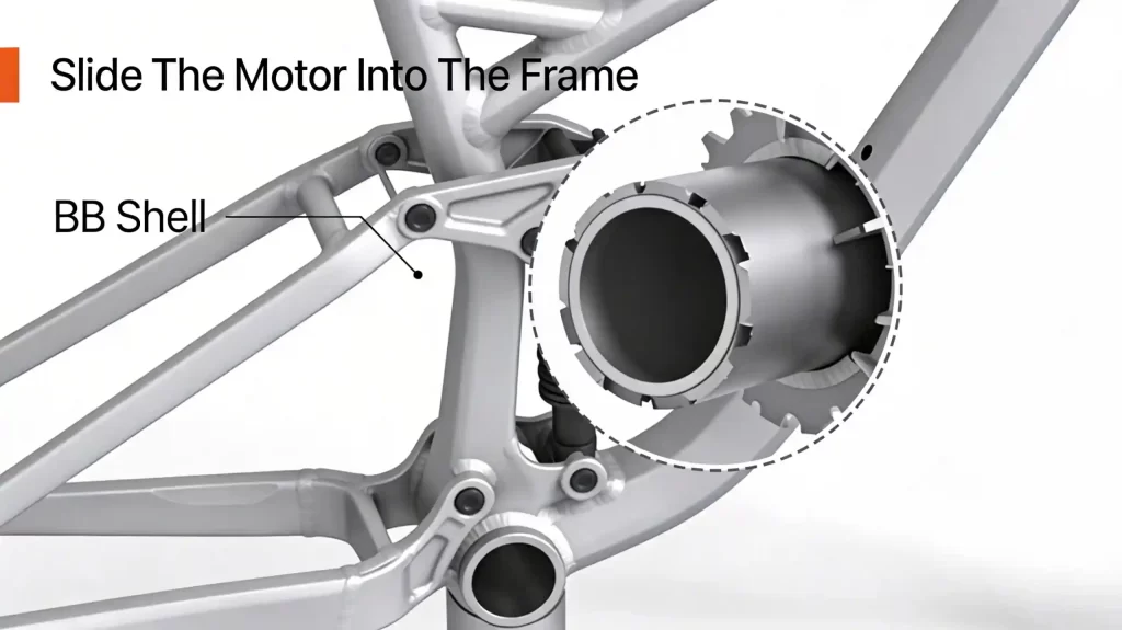
Now you physically insert the mid-drive motor into the BB shell.
⚠️ Important Scope Note
From this phase forward, the focus is entirely on the mechanical installation of the motor unit itself. Battery mounting, display installation, wiring, sensors, and setup all come later. For now, the goal is simply to mount the motor correctly and securely in the frame.
Before you begin this phase, lay out all of the motor-mounting parts on a clean surface so you can identify them first. Most open mid-drive systems include the motor unit, the motor axle, the fixing or anti-rotation plate, the inner main fixing nut, the outer lock ring, any supplied spacers, the chainring, the left and right crank arms, and the crank bolts. If the installer does not identify these parts before starting, it becomes much easier to mount something in the wrong order or in the wrong orientation.
Identify Orientation
The drive side of the motor is the side with the chainring mount or built-in chainring. This faces the right side of the bike (where the old chainring used to be). The motor body is designed to sit below and slightly in front of the BB shell, usually tucked up toward the down tube.
Clarification: many first-time installers make mistakes here because they think the axle orientation is enough. It is not. The chainring side must face the drivetrain side of the bike, and the motor body must finish in its intended resting position under the frame, not hanging at an odd angle.
Insert The Axle
Stand on the right (drive) side of the bike. Line up the motor’s BB axle with the BB shell. Carefully slide the axle through the shell from right to left until the motor’s main flange sits flat against the right side of the BB shell.
Seat The Motor Body
Rotate the motor body upward until it gently contacts the underside of the down tube or sits in the recommended orientation described in your kit manual. At this point, you should be able to hold the motor in place with one hand; it should feel snug but still movable until clamped.
Avoid forcing the axle through if it feels jammed; you should never have to hammer it. A snug slide fit is normal; binding usually means dirt in the shell or misalignment.
⚠️ Important Warning
Inserting the motor is not the same as installing the motor. At this point, the motor is only sitting in position. It is not properly installed until the fixing plate, main nut, and lock ring have all been fitted and tightened correctly.
03 Phase 3 – Fix The Motor In Place

The next step is to clamp the motor tightly to the frame so it cannot rotate under torque.
This is the most important part of the entire motor installation. A motor that is inserted correctly but clamped poorly can rotate under load, damage the frame, damage cables, and loosen over time.
3.1 Install The Mounting (Anti-Rotation) Plate
On the left (non-drive) side of the bike, you’ll see the motor axle protruding from the BB shell.
Identify The Plate
Most open mid-drive kits use a steel plate (often triangular or crescent-shaped) with radial ridges or “teeth” pressed into one face. These ridges are designed to bite into the BB shell edge and stop the motor from rotating.
Orient The Plate Correctly
The ridged/teethed face must point toward the frame, against the BB shell. If the ridges face outward, they cannot grip the shell and the motor will twist under load.
Slide The Plate Onto The Axle
Push the plate over the motor axle until it sits flat against the left side of the BB shell and the back of the motor. Make sure there is no visible gap between the plate, the motor, and the frame; if there is a gap, refer back to the spacer explanation in the pre-installation section and add the correct spacers before continuing.
Install Any Plate Bolts
Some systems have two small bolts that fasten the plate to threaded holes in the motor casing. Thread these in by hand and snug them with a hex key, but do not fully torque yet; final tightening comes after the main nut is in place.
⚠️ Critical Clarification
This “no visible gap” rule must be treated as non-negotiable. If the plate does not sit flush, do not continue tightening and hope it fixes itself. A gap means the plate is not supporting the motor correctly, and the installation should be corrected before moving on.
3.2 Tighten The Main Fixing Nut
This is the critical clamping step.
Thread On The Inner Nut
Take the large round nut supplied with your kit and thread it onto the motor axle on the left side by hand. Spin it on until it meets the mounting plate.
Use The Correct Tool
Use the special multi-notch spanner or socket provided with the kit (or an aftermarket tool meant for this nut). Engage the tool fully in the nut’s notches to avoid slipping.
Clamp The Motor
While holding the motor body in its desired position (usually rotated up toward the down tube), tighten the main nut firmly. Typical torque values are in the 40–60 Nm range, but always follow your kit manual.
Check For Movement
Once tight, try to twist the motor by hand. If it can move at all, the nut is not tight enough, the plate is not seated correctly, or there is a gap behind the plate that needs spacers.
Clarification: the inner/main nut is the part that provides the actual clamping force. It is the nut that holds the motor tight against the frame. The outer ring does not replace this job; it only helps keep the assembly from loosening afterward. The main nut and the plate together are what keep the motor from rocking under power; a loose connection here is the number-one cause of motors rotating and chewing paint or wiring.
3.3 Install The Outer Lock Ring
Most systems add a second ring to lock the main nut.
Thread On The Outer Ring
Screw the lock ring over the main nut by hand until it seats.
Tighten The Lock Ring
Use the proper ring spanner or tool to snug it against the main nut. Its job is to act as a jam nut so the main nut cannot slowly unwind due to vibration.
Final Check
Confirm the plate teeth are biting into the BB shell. You may see small marks on the paint/metal; this is normal and necessary for grip. Verify again that there is no gap between plate and motor and that the motor body is solid.
✅ Phase Completion Check
Before moving to the chainring and cranks, the motor should now be in its final position, the mounting plate should be flush, the main nut should be tight, the outer lock ring should be seated, and the motor should not rotate when you try to move it by hand. At this stage, the mid-drive motor is mechanically fixed to the frame.
04 Phase 4 – Install Chainring And Crank Arms

With the motor clamped in place, you add the parts that your legs and chain will actually drive.
4.1 Mount The Chainring
Position The Chainring
Place the chainring on the motor’s mounting face, aligning bolt holes. Many chainrings are offset; follow your kit’s orientation diagram so the offset goes the correct direction for chainline.
Install Chainring Bolts
Insert all the bolts by hand first so the ring seats evenly. Tighten them in a star pattern with a hex key, then torque to the value given in your manual (often around 8–12 Nm).
Initial Chainline Check
Stand behind the bike and sight along the chainring toward the cassette. The ring should roughly line up with the middle of the cassette cluster; significant inboard or outboard offset can be fine-tuned later with spacers or different rings.
Clarification: at this point you are not trying to perfect the whole drivetrain setup yet. You are only confirming that the chainring is installed in the correct orientation, runs true, and has sensible alignment relative to the rear cassette.
4.2 Install The Crank Arms
Identify Left And Right Cranks
Look for “L” (left) and “R” (right) markings on the inside of the crank arms. The right crank sits on the same side as the chainring; the left crank is opposite.
Fit The Right Crank
Slide the right crank arm onto the motor axle on the drive side, aligning it so it points directly opposite the left crank’s future position (180° apart). Insert the crank bolt and thread it in by hand. Tighten with a hex key or socket, then torque to the recommended value (commonly 35–50 Nm, depending on your system).
Fit The Left Crank
Repeat the process on the non-drive side. Make sure the two crank arms are exactly 180° apart; misalignment here will feel wrong and can damage splines.
Reinstall Pedals
Thread the right pedal clockwise into the right crank. Thread the left pedal counter-clockwise into the left crank. Tighten them firmly with a pedal wrench.
Spin And Clearance Check
Rotate the cranks by hand — they should turn smoothly with no grinding. The crank arms must not hit the motor body or frame. The chainring must clear the chainstay.
⚠️ Clearance Warning
If anything rubs, stop and correct it before riding. This clearance check is part of the motor installation, not an optional extra. If the crank arms contact the motor, or if the chainring sits too close to the frame, the install is not complete yet.
05 Phase 5 – Final Motor Checks

Before you move on to wiring, battery, or display, verify that the motor installation itself is complete and solid.
Motor Stability
Grip the motor housing and try to twist it up, down, and side to side. There should be zero play. If it moves, revisit the main nut, plate seating, and use of spacers.
Plate Contact
Inspect the mounting plate: its ridged face must be flush against the BB shell/motor with no gap. If you see daylight or a visible gap, you need additional spacers or washers so the plate can clamp fully.
Crank Function
Spin the cranks forward and backward. They should feel smooth and consistent. Check that the chainring runs true (no wobble) when viewed from the front.
“Done Means Done” Checklist
The motor installation is complete only if all of the following are true:
- The old chain, crank arms, pedals, and bottom bracket have been fully removed and the shell is clean.
- The motor has been inserted from the correct (drive) side and is sitting in its proper final orientation.
- The anti-rotation plate is installed with the teeth facing the frame and sitting fully flush with no gap.
- The correct spacers have been used if the BB shell width required them.
- The main fixing nut is tightened to the correct torque.
- The outer lock ring is installed and snug.
- The chainring is mounted securely and runs true.
- The crank arms are installed correctly and sit 180° apart.
- Nothing rubs, binds, or moves when checked by hand.
🏁 Core Installation Complete
Now that the mid-drive motor is securely mounted in the bottom bracket shell, the anti-rotation plate is seated correctly, the main fixing nut and lock ring are tightened, and the chainring and crank arms are installed, the core motor installation is complete.
Congratulations — you have finished the most important and most mechanically demanding part of the conversion.
From this point on, the remaining steps are the supporting stages of the build, such as mounting the battery, routing the wiring harness, installing the display and controls, and configuring the system for its first ride.