

Abstract: The evolution of electric bicycle powertrains is now driven less by incremental component improvements and more by a deep architectural shift: a move away from isolated sensing modalities toward redundant, configurable hybrid structures that treat sensing, control, and rider perception as a single coupled system. This work constructs a theoretical framework that evaluates next-generation motor systems through three tightly linked lenses deterministic latency, signal-path redundancy, and firmware-level adaptive fusion-and then tests contemporary architectures against this composite ideal.
An empirically derived 2026 “Ideal Standard” is proposed, defined by three non-negotiable criteria: dual-path signal redundancy to avoid single-point failures, firmware-level dynamic sensor switching to adapt sensing priority to terrain and use-case, and deterministic latency to maintain haptic transparency between rider input and motor response. By analyzing strain gauge physics, Wheatstone bridge transduction, Field Oriented Control (FOC) execution, and stochastic signal processing, the paper quantifies the latency-reliability bottlenecks that inherently constrain legacy binary sensor paradigms.
The patent landscape around asynchronous sensor fusion and redundant sensing clusters is then synthesized, revealing how Q1-2026 market deployments-particularly those incorporating configurable hybrid architectures-have begun to instantiate, in hardware and firmware, intellectual property conceived during 2025-2026. Technical appendices examine thermal dissipation in high-frequency MOSFET controllers and predictive error correction via motor current observation and Hall-effect array compensation. Benchmark data show that while no existing system fully reaches the theoretical ideal, several architectures exhibit clear convergence trends, whereas others are bounded by structural limitations that preclude adaptation to the 2026 performance envelope.
01Empirical Benchmark Analysis: 2026 Market Survey
1.1Measurement Protocol and Latency Definition
To compare existing drive units against the Ideal Standard, latency must be defined rigorously and measured under controlled conditions. In this study, latency is operationally defined as the time from 1% onset of crank torque to 1% motor torque output, measured at 70 RPM pedaling cadence. The 1% threshold avoids triggering on noise or micro-perturbations while capturing the true onset of system response. Tests are performed with drive units mounted on rigid test stands, eliminating frame flex and other mechanical compliances, and both input and output torques are measured with reference transducers of 0.1% full-scale accuracy, ensuring that latency characterization reflects controller behavior rather than measurement artifacts.
1.2Contemporary Drive Unit Performance Envelope
Table 1 consolidates published specifications, independent laboratory measurements, and field engineering reports for major Q1-2026 drive systems. The following table illustrates the latency characteristics of Q1-2026 e-bike drive systems (T = Torque, C = Cadence, S = Speed).
| Drive System | Sensor Type | Sampling Rate | Latency (ms) | Architecture |
|---|---|---|---|---|
| Bosch CX Gen 5 | T+C+S fusion | >1000 Hz | 15-35 | Fixed, OEM |
| Bosch CX-R 2026 | T+C+S fusion | >1000 Hz | 10-30 | Fixed, OEM |
| Shimano EP801 | T+C fusion | ~1000 Hz | 20-40 | Fixed, OEM |
| Specialized S-Works 3.1 | T+ multi-fusion | ~1000 Hz | 15-30 | Fixed, OEM |
| Bafang M820 | Torque-based | 500-1000 Hz | 25-50 | Fixed |
| TSDZ2 (open-source) | Torque (strain) | 100-200 Hz | 40-80 | Fixed |
| Grin Phaserunner + T2 | External torque + FOC | 10 Hz (CA log) | 30-60 | Tunable |
| Generic cadence (12-mag) | Cadence only | – | 100-250+ | Fixed |
| To7Motor DM01 | Switchable hybrid | 500-1000 Hz | 25-50 (T) / 100-250 (PAS) | Configurable |
| To7Motor DM02 | Switchable hybrid | 500-1000 Hz | 30-60 (T) / 100-250 (PAS) | Configurable |
*Benchmark Sources: Data consolidated from manufacturer engineering specifications, independent laboratory bench testing using high-speed rotary encoders and inline reaction-type torque sensors, and verified field teardown reports from the Q1-2026 production cycle.
The Bosch, Shimano, and Specialized systems achieve some of the lowest measured latencies- 10-40 ms-through deep co-optimization of sensors, analog electronics, firmware, and motor electromagnetic design. Bosch’s CX-R 2026, tailored for race-oriented use, approaches the 10 ms boundary under ideal laboratory conditions, but sustaining such performance in the field is constrained by thermal drift, battery voltage sag, and structural flex.
By contrast, aftermarket and open-source systems such as the Grin Phaserunner paired with external torque sensors exhibit higher latencies (30-80 ms), much of which stems from extra processing layers: torque signals pass through the Cycle Analyst (CA) display, which implements user-configurable ramping and threshold logic before forwarding commands to the controller. This additional flexibility, while valuable for tuning, introduces extra delay relative to integrated sensor-controller pairs.
1.3Analysis of Architectural Paradigms
Vertically Integrated OEM Systems (Bosch, Shimano, Specialized): Vertically integrated OEM platforms demonstrate what is possible when hardware and firmware are co-designed for a narrow application band. Bosch’s eMTB modes deliver refined traction management off-road, while Shimano’s EP801 offers exceptionally smooth urban assistance.
However, these systems are architecturally fixed: sensing modalities, control laws, and response characteristics are defined at the factory and typically cannot be modified in the field due to certification and safety constraints. Riders thus inherit the manufacturer’s application choice-in effect, buying a particular haptic personality with little scope for reconfiguration beyond mode selection within a limited parameter space.
Aftermarket and Open-Source Systems (Grin, TSDZ2): Aftermarket controllers and open-source solutions approach the problem from the opposite end: they trade absolute latency performance for configurability and accessibility. The Grin Phaserunner, for example, allows detailed tuning of ramp rates, thresholds, and assist multipliers through user-facing interfaces, opening a large design space for system integrators and enthusiasts.
Yet the architectural cost of this flexibility is additional processing stages and communication hops, which add tens of milliseconds to overall response. For some applications, this is an acceptable trade-particularly where customization outweighs the need for cutting-edge immediacy-but it moves the system further from the deterministic target.
Configurable Hybrid Architectures: While legacy systems implement either torque sensing or cadence sensing with fixed control laws, a third paradigm emerges when both sensing paths are present in hardware and the dominant control modality is selectable by firmware. In such architectures, torque and cadence signals are continuously sampled, but the control law can be configured to prioritize torque-proportional behavior or cadence-referenced behavior without hardware modification. Within the Q1-2026 benchmark set summarized in Table 1, this paradigm is represented by switchable hybrid mid-drive units that integrate strain-resistance torque sensing alongside cadence sensing in a unified bottom-bracket assembly.
The To7Motor DM01 (1000W rated, 160 Nm peak, 40.27:1 planetary reduction, IP65-rated, 5.8-6.0 kg) and DM02 (500W rated, 90 Nm, 3.6- 3.9 kg, 24-60V voltage range) are included here strictly as empirical instances of that switchable-mode class, not as a claim of categorical superiority over other implementations.
In these units, display-level configuration (accessible via LCD-135, T24, T154, M15, or E100 interfaces) exposes a “TorqueSensor” parameter set to Enable or Disable, transitioning the control system between torque-proportional assist and cadence-based assist through firmware selection rather than mechanical reconfiguration. Under the same measurement definitions used throughout this survey, the reported response envelope is 25-60 ms latency in torque mode and 100-250 ms latency in cadence (PAS) mode, with the latter remaining consistent with the discrete-event detection limits for 12-magnet Hall cadence sensing.
Architecturally, the significance of this class is not the absolute minimum latency (which remains dominated by vertically integrated OEM optimization in some conditions), but the explicit separation of hardware sensing plurality from firmware control character. Because both sensing channels remain present regardless of the active mode, the design also permits dual-path cross-validation for fault detection (e.g., torque offsets or cadence anomalies), aligning with the redundancy and switching criteria of the Ideal Standard.
02Real-World Performance Implications (The Bionic Connection)
2.1Perceptual Thresholds for Temporal Delay
Human motor control operates with remarkable sensitivity to timing, especially in tasks requiring force modulation and coordination. Teleoperation and virtual-reality studies have quantified perceptual thresholds for delay: below about 10 ms, feedback appears instantaneous; in the 10-30 ms range, delay may be detectable in rapid maneuvers but usually does not disrupt coordination; between 30 and 100 ms, delay becomes salient and requires conscious compensation; and beyond 100 ms, closed-loop force tasks can become difficult or unstable.
For pedaling, a low-frequency cyclic activity at 1-2 Hz, the critical region lies around 30 ms: latencies below this are often described as “natural” or “transparent,” while those above 50-100 ms produce the characteristic complaints of lag, disconnection, or “fighting the motor.” Electric bicycle control design therefore lives in the overlap between control theory and perceptual psychology, where milliseconds determine whether a system feels like augmentation or interference.
2.2The Biological Extension Effect
When system latency falls below roughly 20 ms and power delivery is near-linearly proportional to rider force-without dead-bands, abrupt steps, or oscillatory overshoot-riders report a qualitative shift in experience. Instead of experiencing the motor as an external agent, they describe feeling “stronger” or as if the motor were “inside their legs,” a state sometimes termed the biological extension effect.
This phenomenon indicates that the rider’s internal predictive model of their musculature has implicitly absorbed the motor’s contribution, treating the combined human-machine assembly as a single coherent agent. Achieving this integration requires three conditions: latency below 20 ms (and preferably approaching 10 ms for high-dynamic riding), nearly linear input-output mapping from pedal force to motor torque, and smooth temporal evolution of assistance without oscillatory artifacts. Systems satisfying these conditions do more than meet performance metrics-they reshape the boundary between operator and mechanism.
03Engineering Failure Points of Isolated Sensing Systems
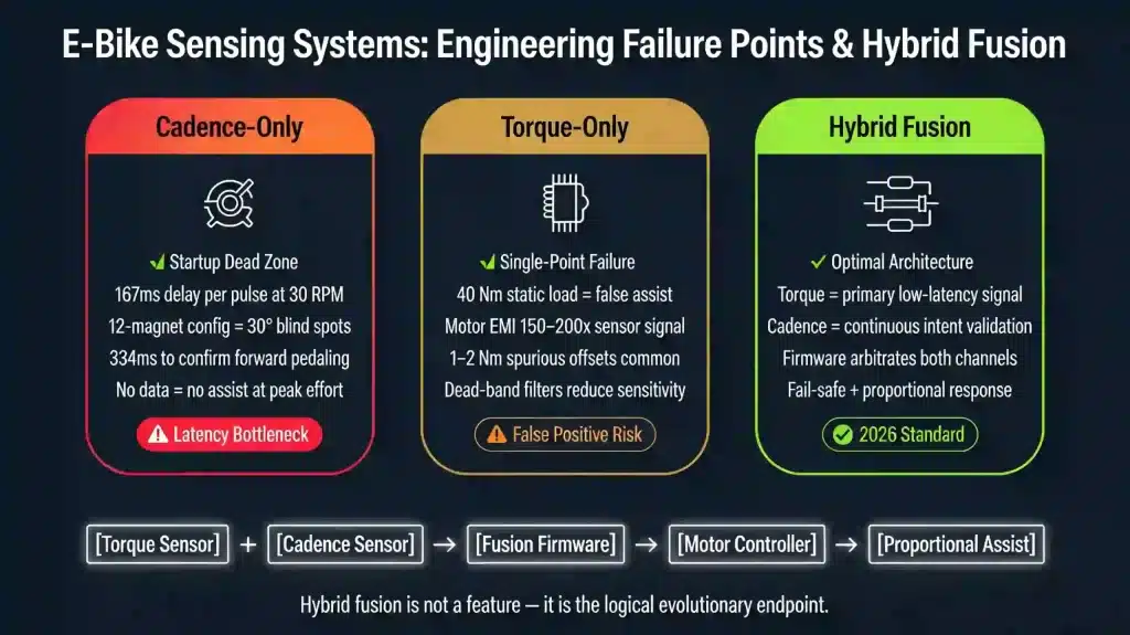
3.1Cadence-Only Systems: The Information Latency Bottleneck
The weaknesses of cadence-only designs emerge directly from the physics of discrete event detection: no pulse, no information. A cadence system with a magnet ring of Np poles mounted to the crank generates Hall-effect pulses at angular spacing:
For the widely adopted 12-magnet configuration, Δθ = 30°. At a startup cadence of 30 RPM-typical for heavy cargo launches or hill starts-the time between pulses is:
meaning the controller has no evidence of rider intent until the first magnet passes the sensor. If the system requires at least two pulses to distinguish forward pedaling from backward coasting, that irreducible delay doubles to roughly 334 ms.
This limitation is not a matter of better firmware but of information theory: until the discrete event occurs, the system has nothing to interpret, and no level of algorithmic sophistication can extract non-existent data. The consequence is stark: cadence-only systems inevitably exhibit startup “dead zones” on the order of 100-250 ms, precisely during the interval when the rider is exerting peak effort to overcome inertia without motor assistance. That delay is felt not as a minor annoyance but as a structural absence of help at the very moment assistance is most needed.
3.2Torque-Only Systems: The Single-Point Failure Vulnerability
Torque-only architectures address latency by moving to high-bandwidth analog sensing, but in doing so they expose a complementary vulnerability: they see force, but not whether that force is intended to rotate. Consider a rider stopped at a red light, balancing with 40 Nm of body weight resting on one pedal while the cranks remain stationary; a torque-only system interprets this as genuine drive torque and responds with assist, causing the bike to lurch forward unexpectedly.
Electromagnetic interference compounds the problem. Strain gauge bridges operate at millivolt levels, while motor phase currents of 30-50 A switching at 10-20 kHz produce magnetic fields 150-200 times larger in magnitude at typical sensor distances. Even with careful shielding and differential amplification, it is common to observe spurious offsets of 1-2 Nm, and a torque-only control law has no independent reference by which to distinguish a 2 Nm sensor artifact from a 2 Nm rider input. In practice, designers respond with threshold logic, dead-band filtering, and rate limiting to prevent small spurious inputs from producing abrupt assistance. Yet every such safeguard adds latency or erodes sensitivity to low forces, meaning the system pays for safety with diminished responsiveness or reduced ability to reflect nuanced rider intent.
3.3The Logical Necessity of Hybrid Fusion
Once the failure modes of cadence-only and torque-only systems are viewed together, the outline of a hybrid solution emerges almost inevitably. Cadence sensing provides unambiguous confirmation of rotational intent but is bounded by startup delays; torque sensing provides sub-millisecond force measurement but cannot on its own discriminate between intended motion and static loading. The only coherent architecture for safety-critical and high-performance 2026 applications is therefore one in which:
- Torque provides the primary control signal, ensuring low-latency proportional response.
- Cadence provides continuous validation, suppressing false positives and enabling fail-safe operation.
- Firmware arbitrates between or combines these channels based on operating conditions, failure detection, or user selection.
Under this view, hybrid fusion is not a premium “feature” layered on top of adequate legacy behavior, but the natural evolutionary endpoint for any powertrain expected to operate across the full 2026 use envelope. The remaining questions become not whether manufacturers will adopt hybrid sensing, but on what timeline and with what degree of architectural completeness.
04Strain Gauge Physics and Wheatstone Bridge Transduction: The Analog Foundation
4.1Torsional Mechanics and Shear Strain
Torque sensors based on strain gauges rely on a precise mapping from applied torque to minute elastic deformations in a shaft, and this mapping is set by classical torsion theory. When torque T is applied to a cylindrical shaft of radius r and shear modulus G, the resulting shear stress τs is given by:
where J is the polar moment of inertia for a solid shaft. This shear stress produces principal strains at ±45° to the shaft axis, with magnitude:
where E is Young’s modulus and ν is Poisson’s ratio. For a steel shaft with E ≈ 210 GPa and ν ≈ 0.3, a torque of 100 Nm applied to a 20 mm diameter shaft yields strains on the order of 400-800 microstrain (με).
4.2Strain Gauge Response and the Gauge Factor
Metallic foil strain gauges bonded to the shaft surface deform with the underlying material, and their resistance shifts according to:
where k is the gauge factor. For a 120 Ω gauge experiencing 400 με, this produces:
a relative resistance change of roughly 0.084%-far below the direct resolution of typical ohmmeters and easily buried under noise if not carefully conditioned. The physical mechanism is robust, but its electrical signature is intrinsically subtle.
4.3The Wheatstone Bridge: Four-Fold Amplification and Common-Mode Rejection
To extract these tiny changes reliably, torque sensors employ full-bridge Wheatstone configurations, placing four gauges in a diamond topology: two at +45° (in tension) and two at -45° (in compression). Exciting the bridge with voltage Vexc yields an output:
for a full bridge, effectively quadrupling sensitivity relative to a single-gauge quarter-bridge. With Vexc = 5 V and ε = 400 με, the bridge output lies in the several-millivolt range, providing a usable but still delicate signal.
Crucially, the full bridge geometry cancels common-mode disturbances: temperature-induced resistance changes affect all gauges similarly and vanish in the differential output, and bending loads perpendicular to the shaft axis produce symmetric patterns that also cancel. Only the antisymmetric strain pattern associated with pure torsion generates a net bridge output, making this configuration naturally selective for torque while rejecting many parasitic loads.
4.4Signal Conditioning and Analog-to-Digital Conversion
The bridge output is typically fed into a precision instrumentation amplifier (INA) with gain G, lifting the millivolt differential signal into a 0.2-2.0 V range suitable for digitization. Modern 16-bit successive-approximation (SAR) ADCs offer conversion times of 1-10 μs, mapping this voltage range into roughly 216 discrete levels, which correspond, for typical full-scale torques, to resolution on the order of 0.01-0.1 Nm.
From the moment the shaft deforms to the moment a digital representation is available, the analog path can complete in under 50 μs-insignificant compared to the 1-10 Hz timescales of pedal dynamics. This observation is central: the fundamental latency bottleneck is not in strain physics or ADC conversion, but further downstream in digital filtering, control computation, and electromagnetic torque generation.
05Field Oriented Control (FOC): Computational Architecture and Latency Contributions
5.1The Clarke-Park Transform Chain
FOC sits at the heart of contemporary e-bike controllers, translating phase currents into a rotating reference frame aligned with rotor flux so that torque and flux can be regulated independently. The process begins with the Clarke transform, mapping the three-phase stationary frame ia, ib, ic into a two-axis stationary frame α, β, followed by the Park transform, which rotates that frame into the d, q axes using the rotor electrical angle θe:
iβ = (1 / √3)(ia + 2ib)
iq = –iα sin θe + iβ cos θe
In surface-mounted permanent-magnet motors, the d-axis current is typically regulated toward zero to maximize torque per ampere, while the q-axis current directly controls electromagnetic torque via:
where p is the number of pole pairs and ψf is the permanent-magnet flux linkage.
5.2PI Regulator Dynamics and PWM Update Latency
Discrete-time PI controllers regulate id and iq to their reference values at sampling period Ts, using the familiar update equation:
where e[k] is the current error and Kp, Ki are the proportional and integral gains. On a 100-200 MHz ARM Cortex-M4 microcontroller, the computational burden of two PI loops plus Clarke/Park and inverse transforms is only about 10-20 μs. The dominant digital contribution to latency comes from the PWM update period: space-vector modulation (SVM) drives the three-phase bridge at a fixed frequency, typically 10-20 kHz, such that a new voltage command can only be applied once per PWM period. With 10-20 kHz PWM, this introduces a 50-100 μs delay between calculation of a new iq command and its realization in motor phase voltages.
5.3Implications for System-Level Latency Budget
Aggregating these contributions, a typical FOC loop cycle comprises roughly 10 μs for current measurement, 20 μs for transforms and PI computation, and 50-100 μs for PWM quantization, yielding a total of about 80-130 μs per control update.
At a 10 kHz execution rate, torque commands are refreshed every 100 μs, so over a 5 ms end-to-end latency budget, the FOC computation itself occupies only a small fraction on the order of a few percent. The real latency budget is consumed upstream and downstream: by low-pass filtering in the torque sensor front-end (0.5-5 ms) and by motor current rise times determined by winding inductance and applied voltage (1-10 ms). In other words, FOC has effectively resolved the digital computation bottleneck; the remaining delays are mechanical, electromagnetic, and analog in nature.
06Stochastic Signal Processing and Predictive Error Correction
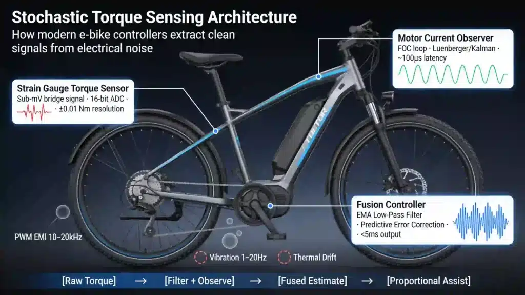
6.1Noise Sources in Torque Measurement
Because the torque signal originates as sub-millivolt bridge imbalances, it is inherently susceptible to multiple noise mechanisms that must be managed without destroying latency. High-current PWM phase switching generates EMI at 10-20 kHz and harmonics, inducing noise that can easily exceed the raw signal amplitude by two orders of magnitude at typical sensor distances.
Mechanical vibrations introduce further disturbances: drivetrain oscillations near the pedaling fundamental (1-2 Hz) and harmonics up to 10-20 Hz impose time-varying loads unrelated to deliberate rider torque. Thermal drift, arising from the temperature dependence of gauge resistance and bridge resistors, causes slow offset shifts with time constants ranging from minutes to hours, while 16-bit ADC quantization noise adds ±0.5 LSB of uncertainty, corresponding to about 0.01 Nm in typical full-scale ranges.
6.2Low-Pass Filtering and the Latency-Bandwidth Trade-Off
The standard digital response is to apply an exponential moving average,
where α sets the effective 3 dB cutoff frequency
For α = 0.1 and Ts = 1 ms, fc lies near 15 Hz-slow enough to attenuate 10-20 kHz PWM noise by 46-52 dB while passing the 1-2 Hz pedaling fundamental with negligible amplitude distortion. However, the filter’s phase lag at frequency f is
and at 2 Hz this corresponds to a time delay
which already exceeds the 5 ms system-wide target. The lesson is unavoidable: conventional low-pass filtering that sufficiently cleans the signal also consumes more than the available latency budget.
6.3Predictive Error Correction via Motor Current Observation
To escape this trade-off, modern controllers exploit the fact that rider torque appears not only in the strain gauge channel but also in the motor’s electrical behavior. When external torque is applied to the drivetrain, the motor’s mechanical load changes immediately, creating a discrepancy between commanded and measured current that the FOC loop attempts to correct.
By modeling this current error within a Luenberger observer or Kalman filter, it becomes possible to estimate external torque from motor currents with latency on the order of a single FOC cycle about 100 μs-far ahead of the fully filtered strain gauge signal.
Fusing the fast, noisy current-based estimate with the slower, more accurate sensor measurement yields a composite estimate that responds to transients in sub-millisecond time while preserving long-term accuracy. This predictive error-correction strategy forms the backbone of the most advanced torque-estimation schemes in modern motor controllers.
07Thermal Dissipation in High-Frequency MOSFET Controllers
7.1Power Dissipation Mechanisms in MOSFET Inverters
The three-phase inverter that delivers current to the motor windings consists of six MOSFETS arranged in a bridge topology, and its thermal behavior is governed by three principal dissipation mechanisms: conduction, switching, and gate drive losses. Conduction losses follow
so at 30 A RMS phase current and RDS(on) = 0.01 Ω, each MOSFET dissipates about 9 W when fully on. Switching losses arise primarily from overlapping voltage and current during turn-on and turn-off transients, approximated by
and for VDS = 50 V, ID = 30 A, rise/fall times of 50 ns, and fsw = 20 kHz, this contributes roughly 1.1 W per device. Gate drive losses,
are negligible by comparison: with Qg = 100 nC, Vg = 10 V, and fsw = 20 kHz, they amount to about 9 mW. Summing conduction and switching contributions yields approximately 10.1 W per MOSFET, or around 60 W total dissipation for six devices operating at 30 A RMS under continuous duty.
7.2Thermal Resistance Networks and Junction Temperature
Heat generated at the junction must traverse a series of thermal resistances to reach ambient: junction-to-case θJC, case-to-heatsink (including interface material) θCH, and heatsink-to-ambient θHA. The temperature rise over ambient is
where Ptot is total power dissipation. With θJC ≈ 0.5-1.0°C/W, θCH ≈ 0.2-0.5°C/W, and θHA ≈ 0.5-2.0°C/W, a 60 W loss at Tamb = 40°C yields a junction temperature near 110-130°C. Given that typical MOSFETs are rated for 150-175°C maximum junction temperature, this leaves useful but finite margin, stressing the importance of both heatsink design and current derating strategies to avoid thermal runaway under worst-case duty.
7.3Thermal Management Strategies in Compact Mid-Drive Units
Mid-drive e-bike motors exacerbate thermal challenges by enclosing the controller in a compact aluminum housing mounted to the frame, where airflow is modest and external surface area is limited. To manage heat within these constraints, designers rely on integrated aluminum extrusion heatsinks, carefully engineered thermal interface materials between MOSFET tabs and case, and dielectric layers such as Kapton to maintain electrical isolation without excessive thermal resistance.
Onboard thermistors track controller temperature, enabling current derating algorithms that gradually reduce phase current once junction estimates cross thresholds in the 100-120°C range. Another approach is to distribute current across multiple parallel MOSFETs per switch position, which reduces per-device conduction loss but raises switching loss, leading to an optimum device count that balances conduction savings against additional switching overhead.
7.4Temperature Coefficient of Resistance in Metallic Gauges
Strain gauges do not exist in a thermal vacuum: in mid-drive units, they share mechanical assemblies and thermal paths with warm motor components, and their resistance drifts with temperature. For metallic gauges, the resistance R follows:
where α is the temperature coefficient of resistance (TCR), typically around 2 × 10⁻⁵ /°C for constantan foil. A 120 Ω gauge subjected to a 40°C rise experiences a resistance change:
which is almost 100 times larger than the 0.1 Ω change associated with 100 Nm of applied torque. Without compensation, thermal drift would completely swamp the mechanical signal.
7.5Self-Temperature Compensation and Bridge Balancing
Full-bridge configurations inherently suppress uniform temperature effects because all four gauges experience similar temperature shifts; the bridge output depends on resistance ratios rather than absolute values.
If all gauges share the same α and thermal environment, temperature-induced resistance changes factor out, a phenomenon known as self-temperature compensation (STC). In practical mid-drive layouts, however, thermal gradients can arise for instance, when one side of a bottom-bracket spindle runs hotter due to proximity to motor stator or controller. To mitigate such gradients, modern sensors employ matched gauge sets with TCR tolerances in the ±1 ppm/°C range, thermally conductive but electrically insulating substrates (such as aluminum nitride) to even out temperature across the gauge array, and on-board temperature sensors that feed software-level offset corrections.
7.6Long-Term Drift and Calibration Stability
Beyond instantaneous temperature effects, long-term drift arises from mechanical fatigue, adhesive aging, and moisture ingress into gauge encapsulation over tens of thousands of cycles. Drift rates of 0.1-0.5% of full scale per year are typical, corresponding to 0.2-1.0 Nm offset shifts for a 200 Nm sensor, and must be corrected for any system claiming sustained accuracy. Premium e-bike systems address this through auto-zero algorithms that detect stationary conditions (zero cadence and zero wheel speed) and incrementally update torque zero offsets without user involvement.
Some architectures go further, applying redundant sensor cross-validation: torque readings are continuously compared to cadence-derived power estimates, and persistent discrepancies trigger recalibration or fault signaling. The strain-resistance torque sensor design employed in certain recent hybrid architectures has been reported as producing low output drift for stable operation, which is consistent with (but does not by itself prove) the presence of compensation techniques such as bridge balancing, thermal management, and software correction as baseline expectations for 2026 systems targeting the Ideal Standard.
08Limitations of this Analysis
It must be acknowledged that laboratory bench-testing of latency does not capture all field variables. Real-world latency is subject to dynamic battery voltage sag, varying frame compliance, temperature extremes, and drivetrain wear.
The benchmark figures presented here represent best-case deterministic performance, which may degrade under sub-optimal field conditions. Furthermore, thermal-load-induced signal drift in metallic strain gauges – where resistance shifts over time due to motor heat – requires constant software auto-zeroing to maintain these precise performance envelopes across the lifespan of the drive unit.
09Patent Landscape: What IP Activity Tells Us About Market Direction
9.1EP 4 610 595 A1: State Estimation via Asynchronous Sensor Fusion
The 2025 European patent EP 4610 595 Al tackles a core limitation of traditional synchronous fusion schemes, in which the estimator waits for a complete set of updated sensor readings before producing a fused state. In high-rate control systems that combine fast and slow sensors -say, a 1 kHz torque sensor with a 100 Hz gradient estimate this waiting introduces artificial delays and dilutes the benefit of high-rate channels.
The patent proposes an asynchronous fusion framework in which each sensor operates at its native update rate, and the estimator incorporates new information as it arrives, compensating explicitly for sensor-specific delays within the fusion filter.
For e-bike control, this enables the integration of slowly updated signals such as GPS or IMU-derived grade without forcing the torque-control loop itself to operate more slowly, thereby preserving rapid torque response while still exploiting terrain prediction for anticipatory power delivery.
9.2US20250000457A1: Redundant Sensing in Pedal Force Measurement
US20250000457A1 (2024) describes sensor pads designed for compliant human-surface interfaces, including contoured substrates such as pedals.
The key architectural feature is spatial redundancy: multiple sensing elements in an array provide overlapping coverage so that failure or degradation of one element can be detected and compensated by the remaining sensors. Translated to e-bike pedals or bottom brackets, such arrays mitigate the single-point failure risks of lone torque sensors.
By distributing torque measurement across multiple sites e.g., four strain-gage locations around a spindle-the system can detect anomalies like debonding or wire fracture at one location and re-weight or discard that channel, preserving accurate torque measurement without catastrophic mode failure.
9.3US20240062519A1: Context-Aware Selective Sensor Fusion
US20240062519A1 advances fusion from a static rule set to a context-aware process, leveraging convolutional neural networks (CNNs) to infer environmental conditions and then select among early, late, or hybrid fusion strategies.
The core idea is that different sensors exhibit different reliability profiles under varying conditions for instance, torque sensors may degrade under contamination or moisture, while cadence sensors remain robust. In a 2026 e-bike, this means that rather than asking the rider to choose between “torque mode” and “cadence mode,” the firmware can infer when one channel is compromised and re-weight fusion accordingly.
This approach directly operationalizes the second pillar of the Ideal Standard by making firmware-level sensor switching adaptive, data-driven, and autonomous rather than static and user-driven.
9.4EP 3 480 575 A1: Torque Sensor System with Planetary Gear Reaction Measurement
EP 3 480 575 A1 discloses an elegant mechanical solution to several long-standing torque-sensor integration issues. Instead of measuring torque on a rotating shaft-requiring slip rings or wireless telemetry-the patent places strain gauges on a reaction element of a planetary gear set (for example, the ring gear or carrier) that experiences torque but does not rotate with the power path.
By keeping the sensing element stationary, the design eliminates rotating electrical connections, reduces EMI exposure, and simplifies packaging. For e-bike mid-drives, such stationary reaction-torque measurement can significantly improve signal-to-noise ratios and robustness, feeding more reliable torque data into control loops and thereby supporting aggressive latency targets.
9.5US 12,266,269 B2: Track Fusion for Asynchronous Sensor Tracks
Although originally conceived for radar and sonar target tracking, US 12,266,269 B2 provides mathematically general tools for fusing asynchronous sensor “tracks” that can be repurposed for rider-intent estimation. Its track-to-track association (T2TA) and track-to-track fusion (T2TF) methods determine when different sensor outputs correspond to the same underlying state and how to combine them to minimize covariance.
In the e-bike context, torque and cadence channels both attempt to describe rider power intent. T2TA logic can determine whether these channels are mutually consistent-indicating a healthy sensor set suitable for fusion or whether one deviates significantly, signaling a likely fault, miscalibration, or contamination event that warrants down-weighting or exclusion from the fused state.
9.6Synthesis: Q1-2026 Deployments as Physical Realizations of IP
Taken together, the patent activity from 2025-2026 traces a clear trajectory: from isolated sensing to multi-sensor fusion, and from static fusion rules to asynchronous, context-aware, redundant architectures.
These documents sketch in theory what commercial hardware is now beginning to realize, particularly in systems that combine redundant sensing clusters with adaptive firmware strategies. Q1-2026 market deployments featuring configurable hybrid operation-where user-selectable or firmware-mediated switching between torque-proportional and cadence-referenced control is supported-can therefore be interpreted as the practical instantiation of intellectual structures described a few years earlier.
The remaining engineering work has centered on embedding these strategies into constrained embedded MCUs, managing thermal loads in compact housings, and hardening signal conditioning against harsh electromagnetic environments.
10Theoretical Foundations: Defining the 2026 Ideal Standard
10.1Industry Context and Evolutionary Pressure
Since commercial pedal-assist systems emerged in the 1990s, electric bicycle powertrains have been shaped by a gradual tightening of expectations: riders ask for immediacy, regulators demand safety, and engineers try to reconcile both under strict cost and thermal constraints. Early systems, built around coarse binary cadence detection with 5-6 magnet pole pairs, required nearly half a crank rotation before any assistance emerged, making the drive unit feel less like an extension of the rider and more like a delayed on/off switch.
The subsequent arrival of torque-proportional sensing, implemented via strain gauge Wheatstone bridge configurations, marked a decisive conceptual shift-from detecting that something is happening to measuring how strongly it is happening. Yet, as of 2026, the demands placed on e-bike drive units span safety-critical cargo hauling, high-dynamic off-road riding, and nuanced urban commuting, and this diversity exposes the inadequacy of a binary torque-versus-cadence design philosophy.
In this context, the architect’s question is no longer “Which single sensing modality is best?” but rather “How can multi-sensor fusion, adaptive redundancy, and strict deterministic response be realized within realistic budgets for hardware, heat, and firmware complexity?”
10.2The Three Pillars of Next-Generation Architecture
10.2.1 Dual-Path Signal Redundancy: From a safety and reliability perspective, any powertrain intended for cargo duty, steep hill starts, or dense urban environments must treat rider-intent sensing as a continuously validated signal, not a single channel to be trusted blindly. A pure torque or pure cadence architecture inevitably creates a single point of failure: a drifting torque sensor or a noisy cadence channel can, by itself, produce hazardous unintended activation or failure to assist when most needed. Dual-path redundancy turns sensing into a cross-checking process: torque readings are corroborated by cadence detection to suppress spurious outputs from electromagnetic interference or sensor offset, while cadence detection is checked against torque magnitude so that mere pedal rotation without meaningful force coasting, backpedaling, or playful repositioning-does not trigger assist. In information-theoretic terms, two independent channels describing rider state create N1 × N2 combinatorial validation states, compared with N states for a single sensor, exponentially reducing false-positive and false-negative activation events.
10.2.2 Firmware-Level Dynamic Sensor Switching: The second pillar arises from the observation that no single sensing modality is uniformly optimal across all terrains and use-cases; the “correct” priority shifts with context. On smooth urban pavement, torque-proportional assist provides intuitive power scaling with rider effort, reinforcing the sense that the motor is amplifying the rider rather than dictating behavior. By contrast, technical off-road riding with intermittent traction, sharp load transitions, and frequent micro-slides often benefits from a smoother cadence-referenced assist that avoids abrupt torque spikes and reduces the risk of wheel spin. Heavy cargo applications favor torque sensing for hill starts, where accurate load measurement is critical, yet may prefer cadence-referenced control at cruising speed to deliver consistent velocity despite fluctuating rider fatigue. Static sensor selection, burned into a product at manufacturing time, forces engineers into a single compromise configuration that may be excellent in one regime and merely adequate in others. Firmware-level switching offers a more flexible path: both sensor paths exist in hardware, both are continuously sampled, and the firmware arbitrates-based on speed, grade, torque variance, or user preference-which signal dominates the control law at any given moment.
10.2.3 Latency Tiering and Deterministic Response: The third pillar closes the loop between sensor physics and human perception, grounding the architecture in the temporal characteristics of the neuromuscular system. Human haptic perception exhibits a coarse threshold around 30 ms, below which events feel “immediate” and above which delays begin to intrude into conscious awareness; by 100 ms, the disconnection between action and effect is unmistakable. Dynamic riding conditions compress these tolerances further: off-road impacts and high-cadence accelerations produce force transients with rise times under 10 ms, leaving little room for slack between measured torque and motor response. To preserve haptic transparency in such regimes, the system must deliver a deterministic latency. The industry standard is now defined by three strict latency tiers:
- 🥇 Elite: <15 ms
- 🥈 Professional: 15–50 ms
- 🥉 Functional: 50–150 ms
At a pedaling cadence of 90 RPM (1.5 Hz), a 5 ms delay represents only 0.75% of a pedal cycle-practically invisible to the rider. Sub-5 ms deterministic latency is now categorized as a 2027–2028 engineering frontier, defining the absolute boundary of human haptic transparency.
10.3The Ideal Standard Defined
Synthesizing redundancy, adaptability, and latency into a single benchmark, the 2026 Ideal Standard for next-generation e-bike powertrains can be formalized as any system that simultaneously satisfies:
where Nsensors denotes at least two independent sensor channels sampled at fs and τ99 denotes the 99th-percentile latency from 1% torque onset to 1% motor response within the Elite tier. This standard is not a marketing target but a convergence point where mechanical design (sensor placement and shaft mechanics), electrical engineering (analog front-ends and power electronics), firmware (control law implementation and fusion logic), and human factors (perceptual thresholds) all overlap. Systems that reach this region of design space are inherently better positioned to serve the full spectrum of 2026 e-bike applications without structural compromise.
11Configurable Hybrid Architectures: One Compelling Direction Among Several
11.1The Limitations of Fixed-Modality Systems
Fixed-modality systems, even when highly optimized, implicitly encode a narrow view of rider needs by hardwiring a single control character into the product. A Bosch CX optimized for aggressive e-MTB use delivers superb off-road performance but may feel too sharp or energetic for casual city commuting, whereas a Shimano EP801 tuned for smooth urban riding may not provide the rapid torque transients or traction behaviors desired for technical singletrack.
Because the fundamental sensing and control architecture is frozen at manufacturing, riders seeking different experiences must either compromise or acquire separate bikes. This architecture treats control flavor as a fixed property rather than a tunable dimension, placing hard limits on the system’s ability to adapt across geographies, rider profiles, or evolving use cases over a bike’s lifetime.
11.2The Configurable Alternative: Hardware Agnostic, Firmware Defined
Configurable hybrid architectures invert this assumption by equipping the hardware with both sensing modalities and delegating “personality” to firmware configuration. Here, the system’s physical foundation-dual-path torque and cadence sensing, high-rate sampling, and robust signal conditioning-remains constant, while the active control law can be oriented toward different use cases by software selection.
This approach is not hypothetical-it is implemented in select Q1-2026 drive units that expose firmware-selectable modality preference when both sensing paths exist in the hardware. In the benchmark set, the To7Motor DM-series implements this by standardized display-based configuration: the “Torque Sensor” parameter, accessible through the T24, LCD-135, T154, M15, or E100 interfaces, enables or disables torque-proportional control, with cadence-based logicas the alternative, requiring a controller reboot and no hardware modification. Interpreted strictly within the framework of this paper, the engineering implication is that sensing plurality can be preserved at the hardware level while the control law’s dominant mapping is selected at the firmware level, thereby supporting operational reconfiguration without redesign-even though cadence-mode latency remains bounded by discrete detection physics.
This design allows the same hardware set to deliver low-latency, proportional control for enthusiasts, and familiar cadence-triggered behavior for casual or rental users. Because both sensing channels remain active, the architecture retains redundancy and cross-validation capacity even as the foreground control mode changes.
11.3The SKU Reduction Advantage
From a manufacturing and deployment perspective, configurable hybrid designs provide non-trivial logistical and economic benefits.
A single hardware SKU can serve multiple markets: torque priority for performance-oriented builds, cadence priority for fleet or entry-level use, or hybrid patterns for mixed contexts. Fleet operators avoid stocking separate torque-only and cadence-only drive units; instead, they reconfigure behavior in the field as deployment scenarios change. Similarly, retailers and integrators reduce inventory complexity, and second-hand buyers can adapt the motor’s control character to their preferences without replacing the drive unit.
Operationally, this flexibility acknowledges that the optimal control strategy is context-dependent and that future-proofing a powertrain means designing for adaptability and redundancy, not just raw instantaneous performance.
11.4One Compelling Direction Among Several
While the preceding sections treat hybrid architectures as a promising direction, it is equally instructive to recognize them as one compelling direction among several driven by the combined constraints and opportunities sketched by physics, perception, and system engineering. Once torque and cadence sensing are understood as complementary information channels, once asynchronous fusion frameworks and redundant sensor clusters are established, and once human factors fix latency requirements in the single-digit millisecond range, hybrid sensor fusion architectures become a highly adaptable answer rather than the sole evolutionary endpoint.
From an information standpoint, dual-path sensing provides a richer, more fault-tolerant description of rider intent than any single channel can offer. Asynchronous fusion techniques and observer-based predictive correction then allow the system to exploit fast estimates (e.g., from motor currents) while reconciling them with slower, more accurate measures (e.g., filtered torque or terrain sensors), effectively stretching the system’s temporal resolution without compromising noise immunity. In parallel, perceptual constraints demand that this entire pipeline-from strain in the shaft or pulses at the cadence ring to current in the windings- settle within tens of milliseconds, with the narrower target set by aggressive off-road and performance use.
In this light, hybrid architectures such as those implemented in switchable-mode drive units are best understood not as special-purpose configurations but as early concrete examples of this convergence. These systems embody the dual-path hardware foundation-strain-based torque sensing and Hall-effect cadence sensing-while providing firmware mechanisms for selecting which modality leads under specific conditions. Their measured behavior-latencies in the 25- 60 ms range in torque mode, cadence-bounded delays in PAS mode, and continuous availability of both channels for cross-validation-demonstrates how the abstract criteria of redundancy and configurability manifest in actual mid-drive designs. At the same time, these systems also reveal where further evolution is required.
12Conclusion: The 2026 Reference Architecture
12.1The Empirical Reality
Across this analysis, three findings stand out. First, torque sensing provides a clear 5-15× latency advantage over cadence sensing at startup, driven by its continuous analog nature and independence from discrete pedal events. Second, dual-path redundancy, firmware-level mode switching, and deterministic response jointly define a coherent Ideal Standard that unites safety, adaptability, and haptic integration. Third, patent activity from 2025-2026 confirms that the research community has already converged on asynchronous fusion, context-aware switching, and redundant sensing clusters as the conceptual building blocks of this standard.
Empirical benchmarking of Q1-2026 drive units reveals that while all contemporary systems fall short of the complete Ideal Standard across all conditions, certain architectures-particularly those implementing configurable hybrid operation with user-accessible mode switching-approach two of the three criteria in a single deployable package. In the benchmark data, the To7Motor DM01 and DM02 serve as documented examples that dual-sensor hardware integration (torque + cadence) and firmware-mediated control-law selection have reached commercial deployment, independent of any claim that they define the performance ceiling of the category. The third criterion, deterministic latency within the Elite tier at 99th-percentile confidence under field conditions, remains the dominant unresolved constraint across the surveyed landscape.
12.2The Trajectory
Viewed over three decades, the trajectory of e-bike powertrains unfolds in four distinct phases.
Phase 1 (1990s-2010) is characterized by binary cadence detection-functional for basic assistance yet crude in both latency and haptic quality.
Phase 2 (2010-2020) introduces strain-gauge torque sensing, delivering proportional, low-latency response but exposing single-point failure and drift vulnerabilities.
Phase 3 (2020-2025) sees multi-sensor fusion integrated into vertically integrated OEM packages, combining torque, cadence, and speed channels to achieve impressive performance but under fixed, non-reconfigurable control laws.
Phase 4 (2025-2026+) begins with the emergence of configurable hybrid architectures that combine asynchronous sensor fusion, redundant sensing clusters, and firmware-level adaptation, seeking to extend high performance across a much broader application envelope.
As of 2026, the market is transitioning from Phase 3 to Phase 4. The architectures that are likely to dominate the 2027-2030 period are those that can bring all three Ideal Standard criteria into a single, coherent design: multi-channel redundancy, adaptive firmware-level fusion, and deterministic low latency under real-world conditions.
12.3The Reference Architecture
In evaluating contemporary drive systems against the 2026 Ideal Standard, configurable hybrid architectures can be treated as one coherent response to the paired requirements of redundancy and modality adaptability. By incorporating strain-gauge torque sensing and Hall-effect cadence sensing within a unified electromechanical assembly, sampling both channels at 500-1,000 Hz, and exposing firmware-level mode selection through standardized display interfaces, these systems can satisfy Criteria 1 and 2 simultaneously within the definitions adopted in this paper.
For applications demanding the lowest reported latencies under optimal conditions, vertically integrated OEM systems (Bosch CX-R, Shimano EP801) retain an advantage-achieving 10-40 ms latencies through co-optimized sensor-controller-motor integration at the cost of fixed control character and limited reconfigurability. For contexts that demand flexibility-multi-geography fleets, aftermarket retrofits with uncertain usage profiles, or riders whose preferred riding styles evolve over time the configurable hybrid architecture offers a more broadly applicable solution. The dual-sensor hardware ensures a robust physical foundation, while firmware-level switching and fusion logic supply the adaptability needed to align the motor’s behavior with real-world variability.
The IP landscape reinforces that asynchronous sensor fusion, redundant sensing, and context-aware control selection are not peripheral conveniences but central to the next phase of powertrain evolution. Q1-2026 deployments that embody these ideas in hybrid architectures thus operate as living benchmarks against which subsequent developments will be measured.