
Code Breakdown: [cite: 88]
• 03: DM03 Series
• A / H: Square Axle / Spline Axle
• 035: Power Rating (035 x 10 = 350W)
• 239: Production Date (e.g., Sept 2023)
• 00001: Sequential Serial Number
| Component | Specification | Qty |
|---|---|---|
| Drive Unit | DM03 / DM03H Series | 1 |
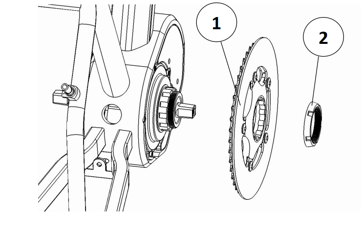
| Chainring | Standard 42T (38-54T optional) | 1 |
| Left & Right Cranks | 170mm | 1 Pair |
| Locknut | M42 x 1.5 | 1 |
| Axle Screw | M8 x 1 x 15 | 2 |
Please read every step carefully. Incorrect installation can result in permanent damage to the motor or your bicycle frame.
Before you begin, ensure you have the following tools ready:
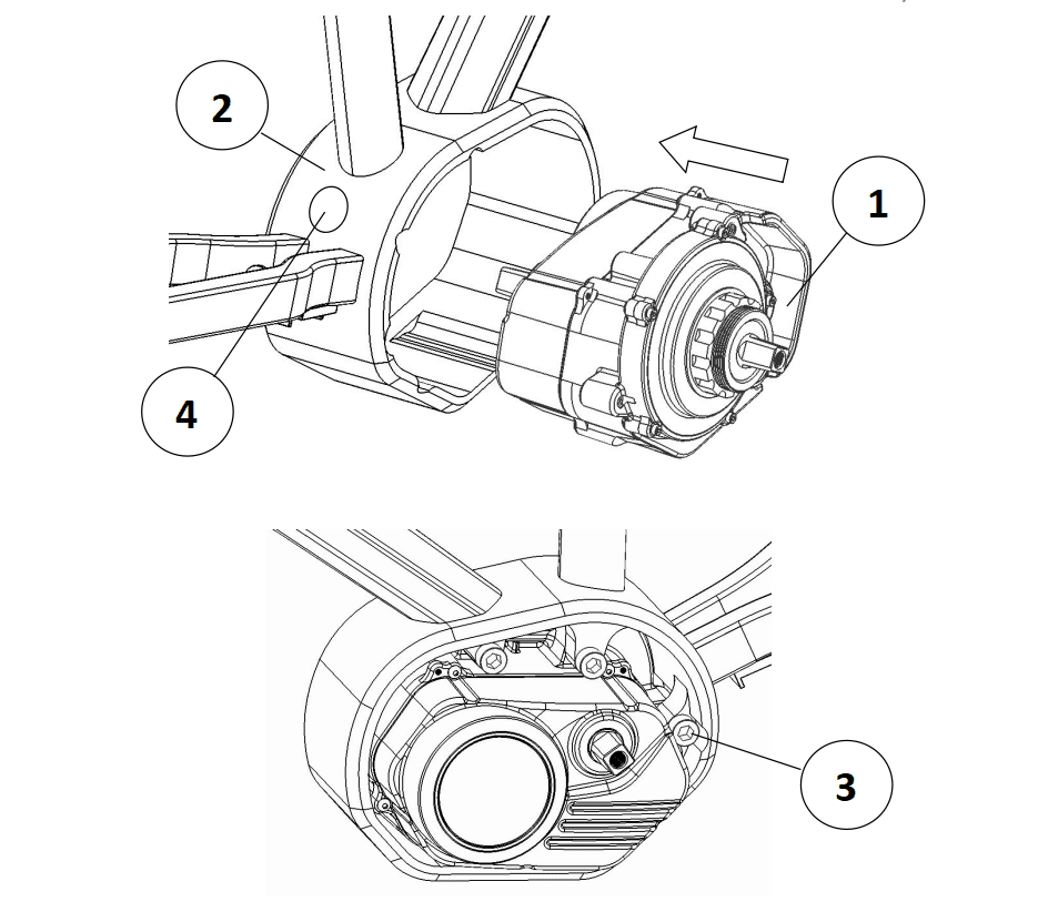
Position the motor unit so the arrow on the casing points directly toward your mounting bracket. Align the three M8 threaded holes on the motor with the three clearance holes on the bracket.
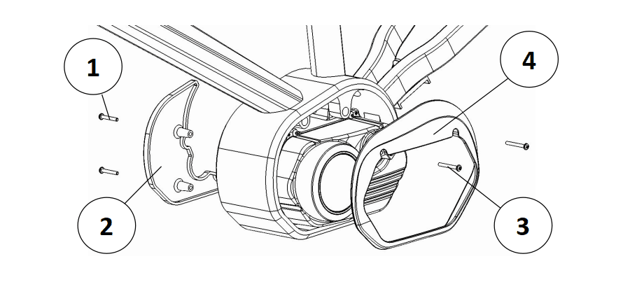
Install the protective covers to prevent debris from entering the motor assembly:
This step requires the Special Wrench included in your kit.
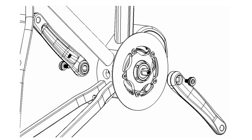
Slide the 170mm left and right cranks onto the axle. Tighten the bottom bracket screws (M8x1x15) using your 8mm Allen wrench.
Safety Torque: Tighten these to 35-40 Nm. If these are loose, the cranks can fall off during a ride. Check these after your first 50 miles.
Model: SVS1
Model: SVS2
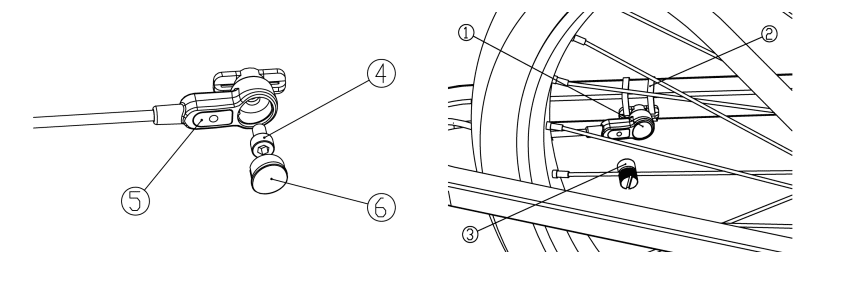
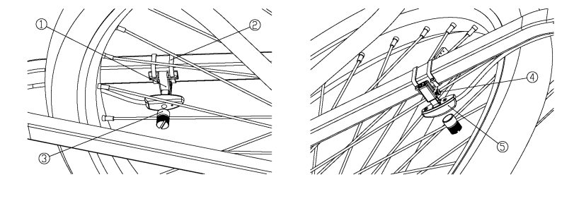
Connect the E-Bus cable, Battery, and Speed Sensor to the matching motor connectors. The other ends of the E-Bus cable connect to your display, throttle, and brakes.
Achieve 2-5mm distance between sensor mark and magnet.
Proper function maintained within 15mm max distance.
Note: For optimal performance and longevity, ensure the storage area is free of corrosive gases.