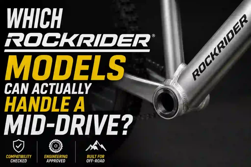
Which (Rockrider) Models Can Actually Handle a Mid-Drive?
SHARE: ON
The definitive engineering reference for electrifying the Decathlon Rockrider ST 540 hardtail platform. This document covers bottom-bracket interface mechanics, drivetrain alignment, frame structural behavior, motor integration, off-road performance, reliability, and OEM-grade maintenance protocols.
01. Compatibility Overview & Suitability Key
The success of any mid-drive conversion is determined before a single component is ordered. The Rockrider ST 540 is engineered around a 6061 aluminium frame with a BSA 73mm threaded bottom bracket — the strongest, most predictable conversion interface available. Aluminium’s high isotropic strength permits the full 160 Nm output of the DM01 without delamination risk. The single variable that changes across generations is rear hub spacing.
Status
Engineering Definition
Status🟢 Perfect
Engineering DefinitionIdeal conversion candidate. Drop-in. Minimal or no adapter hardware.
Status🟡 Moderate
Engineering DefinitionRequires specific hardware (bushings, spacers, offset chainring) and care.
Status🟠 Advanced
Engineering DefinitionComplex geometry or carbon. DM02-only protocol applies.
Status🔴 Not Recommended
Engineering DefinitionHigh structural or geometric risk. Do not attempt conversion.
Verdict Note: All ST 540 generations are Perfect/Recommended drop-in candidates on the threaded BSA shell. The Boost-spaced ST 540 S is rated Moderate solely because it requires a 9mm offset chainring for chainline correction.
02. Platform Engineering Analysis
The ST 540 is a hydroformed-aluminium hardtail engineered for cross-country and trail riding. Its reinforced bottom-bracket region, triangulated rear, and rigid main triangle make it a structurally ideal motor anchor — the inverse of a compliant endurance frame. Pedaling loads, off-road impact, and torsional rigidity all converge at the BB junction where the motor mounts.
Rear Hub: 9×135mm QR (orig/V2) or 148×12mm Boost (S)
Frame Weight: ≈ 2.1 kg (size M, bare frame)
03. Variant Compatibility Matrix
Identify your exact generation before ordering. All share the BSA 73mm threaded shell; only rear hub spacing — and therefore chainline hardware — differs.
A. Model Lookup
Variant
Generation
Material
Bottom Bracket
Rear Hub
Status
Motor
Engineering Notes
VariantST 540 (Original 27.5″)
Generation~2019–2022
Material6061 Aluminium
Bottom BracketBSA 73mm Threaded
Rear Hub9 × 135mm QR (Non-Boost)
Status🟢 PERFECT
MotorDM01 / DM02
Engineering NotesDrop-in. 0mm offset chainring aligns to 135mm chainline. Route BB-exit cables around the motor block.
VariantST 540 V2
Generation~2021–2023
Material6061 Aluminium
Bottom BracketBSA 73mm Threaded
Rear Hub9 × 135mm QR (Non-Boost)
Status🟢 PERFECT
MotorDM01 / DM02
Engineering NotesClutch derailleur improves chain retention under torque. DM01 shift-sensor recommended for the wide 11–48T cassette.
VariantST 540 S / Switch&Ride
Generation~2023+
Material6061 + 6013 Aluminium
Bottom BracketBSA 73mm Threaded
Rear Hub148 × 12mm Boost Thru-Axle
Status🟡 MODERATE
MotorDM01 / DM02
Engineering NotesBoost rear pushes the cassette 3mm outboard — a 9mm offset chainring is mandatory to restore chainline. Verify 27.5/29 swingarm clearance.
In a TOSEVEN conversion the original crankset, spindle, and bearings are removed entirely. The motor axle slides through the empty shell and a steel lockring clamps the motor body against the flat shell faces. The bottom bracket ceases to be a bearing housing — it becomes the primary structural anchor for up to 160 Nm of rotational force.
Axle fit: The 33.5mm TOSEVEN axle slides through the BSA shell with near-zero radial play — no reducer bushings needed.
Clamp interface: Steel locknuts thread onto the axle and clamp against the flat outer shell faces; preload 60–80 Nm on aluminium.
Reaction torque: The anti-rotation bracket transfers reaction torque into the chainstay/downtube, preventing axle spin and thread damage.
Face preparation: Inspect shell faces for parallelism; clean threads and apply anti-seize before installation.
05. Drivetrain Engineering
Mid-drive torque routes through the existing chain and cassette, multiplying drivetrain stress. Chainline optimization is the single most important factor for shifting quality and component longevity. The ST 540’s hub spacing dictates the required chainring offset.
A. Chainline Optimization
135mm QR (Original / V2): Standard non-Boost chainline. A 0mm offset chainring keeps the chain straight across the cassette.
148mm Boost (ST 540 S): Cassette sits 3mm outboard. A 9mm offset chainring is mandatory to restore chainline and prevent chain drop under power.
B. Drivetrain Compatibility
Compatible Drivetrains: Shimano Deore, SLX, XT, CUES, SRAM NX, GX, SX, MicroSHIFT Advent X, 1x wide-range, and Clutch derailleurs.
Prefer a clutch rear derailleur and a steel wide-range cassette for high-torque longevity. Always shift with momentary power-cut (automatic on DM01, manual on DM02) to protect sprocket teeth and chain pins.
06. Frame Structural Engineering
6061-T6 aluminium offers high isotropic strength and predictable fatigue behavior — it carries torsional and compressive motor loads without the interlaminar shear vulnerability of carbon. This is precisely why the DM01 is approved on the ST 540 and prohibited on carbon frames.
A. Load Path Analysis
Down tube: Carries compressive load and braces the motor against rotation.
BB shell junction: Convergence of downtube, seat tube, and chainstays — the torque reaction node.
Chainstays: React torsional load; maintain motor housing clearance on small sizes.
Weld HAZ: Heat-affected zones around the BB are fatigue-monitored at service intervals.
Torsional rigidity: High lateral stiffness keeps motor-to-frame micro-movement near zero.
Fatigue life: Aluminium tolerates millions of cycles at conversion load levels with periodic torque audits.
Precision Torque Wrench: Mandatory. Required to verify lockring and bracket preload to spec.
Protective Cable Conduit: Recommended. Shields BB-exit shift/brake cables from the motor casing to prevent torque-sensor drift.
C. Critical Operational Rules
The 3-Second Calibration Rule: After powering the T24 display, keep all weight off the pedals for at least 3 full seconds. The torque sensor uses this window to establish its zero-load baseline. Violating it corrupts the reference and causes erratic power delivery.
Manual Shifting (DM02): The DM02 has no shift sensor. Consciously pause pedal input for a split second before every gear change to drop motor power to zero and protect the drivetrain. The DM01’s integrated sensor does this automatically.
Chainline Verification: Confirm front chainring offset matches rear hub spacing — 0mm for 135mm QR, 9mm offset for 148mm Boost. A diagonal chainline under motor torque causes chain drop and accelerated wear.
Cable Routing Discipline: Route all BB-exit cables around the motor block with protective conduit before tightening. A pinched cable mimics leg pressure on the torque sensor, producing power surges.
08. Off-Road Performance Engineering
Mid-drive placement keeps mass low and central, preserving the ST 540’s XC handling. Torque is delivered through the drivetrain, so traction tracks rider cadence and gear selection rather than a fixed hub speed.
A. Handling Characteristics
Climbing efficiency: Central mass + gear-multiplied torque make technical climbs the platform’s strongest discipline.
Weight distribution: Low BB-mounted motor lowers the center of gravity, improving cornering stability.
Power modulation: Torque-sensor assist scales smoothly with pedal input for predictable traction on loose terrain.
Descending control: Rigid hardtail rear and the added low-mounted motor mass keep the bike planted at speed.
Battery efficiency: Drivetrain gearing lets the motor stay in its efficient RPM band, extending range on mixed terrain.
1. Assuming Boost spacing needs no chainline correction: On the ST 540 S (148mm Boost), installing a flat 0mm offset chainring pulls the chain at a severe outward angle. The derailleur skips and the chain drops under power. Use the 9mm offset chainring.
2. Pinching BB-exit cables against the motor: The ST 540 routes shift and brake cables near the BB shell. Trapping them between the motor casing and frame mimics leg pressure on the torque sensor, causing erratic surging power that only clears once cables are rerouted.
3. Skipping the anti-rotation bracket: The BSA threads carry the motor radially, but the reaction torque (up to 160 Nm on the DM01) must be braced. Without the anti-rotation bracket the axle spins and damages the shell threads.
4. Under-braking a high-torque build: The motor adds ~8 kg and higher sustained speed. Verify the stock hydraulic brakes and rotor size are adequate before running the DM01 at full output; upsize rotors if needed.
5. Ignoring the 3-second calibration: Resting feet on the pedals at power-on corrupts the zero-load baseline, producing jerky, unpredictable assist on every subsequent ride.
12. FAQ & Troubleshooting
A. Is the Rockrider ST 540 a good mid-drive conversion candidate?
Yes. Every ST 540 generation uses a 6061 aluminium frame with a BSA 73mm threaded bottom bracket — the safest and most mechanically sound conversion interface. It accepts both the TOSEVEN DM01 (160 Nm) and DM02 (90 Nm) as a drop-in, with no reducer bushings required.
B. Can I run the high-power DM01 on the ST 540?
Yes. Because the ST 540 frame is aluminium (not carbon), the DM01’s 160 Nm output is fully approved. Aluminium has high isotropic strength and tolerates a 60–80 Nm lockring torque. Only carbon frames prohibit the DM01.
C. Does my ST 540 use Boost or non-Boost rear spacing?
The original ST 540 and ST 540 V2 use 9×135mm QR (non-Boost). The newer ST 540 S / Switch&Ride uses 148×12mm Boost thru-axle. Boost spacing pushes the cassette 3mm outboard, so a 9mm offset chainring is required to keep the chainline straight.
D. Do I need a shift sensor for the DM02?
No. The DM02 produces 90 Nm and does not include one. You act as the shift sensor: ease off the pedals for a split second before each shift. The DM01 includes a mandatory integrated shift sensor because its 160 Nm would otherwise snap the chain during a loaded shift.
E. Why is my motor delivering jerky or surging power?
Two common causes: (1) the 3-second calibration was violated at power-on — restart with feet off the pedals; (2) a BB-exit cable is pinched against the motor casing, fooling the torque sensor. Reroute cables with protective conduit.
F. Will the motor housing clear the chainstays on smaller frame sizes?
The ST 540’s BSA 73mm shell and standard MTB chainstay spacing clear both motor housings. On the smallest frame sizes, physically verify the motor rotates fully upward against the downtube without contacting the chainstays before final torque-down.

 The success of any mid-drive conversion is determined before a single component is ordered. The Rockrider ST 540 is engineered around a 6061 aluminium frame with a BSA 73mm threaded bottom bracket — the strongest, most predictable conversion interface available. Aluminium’s high isotropic strength permits the full 160 Nm output of the DM01 without delamination risk. The single variable that changes across generations is rear hub spacing.
 The ST 540 is a hydroformed-aluminium hardtail engineered for cross-country and trail riding. Its reinforced bottom-bracket region, triangulated rear, and rigid main triangle make it a structurally ideal motor anchor — the inverse of a compliant endurance frame. Pedaling loads, off-road impact, and torsional rigidity all converge at the BB junction where the motor mounts.
 In a TOSEVEN conversion the original crankset, spindle, and bearings are removed entirely. The motor axle slides through the empty shell and a steel lockring clamps the motor body against the flat shell faces. The bottom bracket ceases to be a bearing housing — it becomes the primary structural anchor for up to 160 Nm of rotational force.
 Mid-drive torque routes through the existing chain and cassette, multiplying drivetrain stress. Chainline optimization is the single most important factor for shifting quality and component longevity. The ST 540’s hub spacing dictates the required chainring offset.