Utilizes a robust 195mm outer diameter stator core paired with high-grade 45-grade high magnetic steel
Precision Control
Integrated Hall effect sensors provide accurate real-time motor positioning, enabling smooth and responsive power delivery. Fully compatible with left-sided 6-hole disc brake systems for enhanced safety.
Built to Last
23 Motor Pole Pairs. 195mm Outer Diameter Stator Core.
Note: Not designed for underwater use or strong acid/alkali environments.
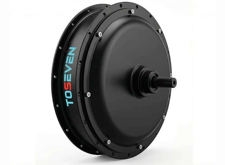
Ditch the roar of chains and experience the silent, high-speed efficiency of the ZM05-175DL hub motor. Engineered with 23 motor pole pairs and 45-grade high magnetic steel , it delivers an exceptional 120N.m of torque right off the line. Whether you’re tackling steep hills or hauling heavy cargo, the ZM05 provides smooth, hushed operation under 60dB for the ultimate fat-tire e-bike experience
Specs & Dimensions
Installation
Maintenance
Technical Specifications (ZM05-175DL)
Power Output
Rated Power: 3000W
Peak Power: 4000W
Rated Voltage: 72V
Max Torque: 120 N.m
Rated Current: 50A
Max Efficiency: 82%
Motor Engineering
Stator Core: φ195mm Outer Diameter (300#)
Magnet Steel: 3mm-thick 45-grade
Magnet Specs: 45*13.65*3
Pole Pairs: 23 pairs
Load Speed: 700 ±10 RPM
No-load Speed: 860 ±10 RPM
Physical & Mounting Dimensions
Motor O.L.D: 175mm ±1
Total Axle Length: 250±1mm
Disc Brake Spacing: 16±0.5mm
Freewheel Chain Line: 30.5mm
Spoke Hole Circle (PCD): 233mm
Wheel Size: 20″ Fat-tire
Net Weight: 9.4 KG
Axle Thread: M16*1.5
Freewheel Thread: B1.375*24-6g
Cable Routing: Left-sided
Motor Structure Diagram:
Installation & Commissioning
Before installation, verify that the controller and motor are compatible (rated voltage, control angle, and specs).
Included Accessory Kit
Component
Specs (mm)
Qty
Material
Flat Washer
24*16*2.4
2
Dacromet
Rotating Stopper
16*10*4
2
Dacromet
Flange Nut
M16-1.5
2
Dacromet
Rubber Sensor
Nonporous
2
Rubber
Controller Connection Diagram
Reference wiring: Phase (Blue, Green, Yellow), Power (Red/Black), and Hall Sensor connectors.
Setup Procedure
Secure Mounting: Install onto the frame ensuring all fasteners are properly tightened.
Wiring: Connect phase wires, throttle, and Hall sensor wires to the controller as indicated in the diagram.
Commissioning: Power on the system, unlock the electric door lock, and test the motor via the handlebar.
⚠️ CRITICAL WIRING ALERT Correct connection of the Hall sensor (+5V Red, Ground Black) is mandatory. Reversing these may cause permanent damage. Avoid touching connectors while powered.
Annual Maintenance Recommendations
The following maintenance should be performed annually by qualified professionals:
Fastener Inspection: Check the tightness of all screws on each motor component.
Wear Inspection: Inspect the contact surface between the magnet and the motor’s front cover.
Sensors: Verify the proper operation of the Hall effect sensor.
Connectivity: Examine connections between the motor power line and Hall sensor line.
Lubrication: Assess the planetary gear set and apply high-quality lubricating grease if necessary.
Safety & Operating Precautions
Always turn off the power switch immediately when the motor is not in use.
Repairs must be performed exclusively by qualified professionals.
Ensure the power is turned off before any maintenance work.
Environment: Do not operate in environments with strong acids/alkalis or underwater.
Troubleshooting Guide
Malfunction
Cause Analysis
Solution
Motor fails to rotate
1. Controller incompatibility
2. No power supply
Inspect/replace controller or verify circuit connections